ASU Campus 1 Scenario
DeepMIMO
ASU Campus 1
- An outdoor scenario based on a section of the ASU Campus in Tempe, Arizona
- GPS bounding box [33.418081, 33.420961, -111.932875, -111.928567]
(KMZ available) - 1 base station and 131,931 users are available!
- Dataset is available at operating frequency 3.5 GHz
Key components
- 1 base station (BS): BS1
- BS1 details:
- Height: 22 m
- (x,y,z) = (166, 104, 22)
- Latitude and longitude coordinates: [33.4203, 111.9286916]
- Each antenna array element at the BS is modeled as an isotropic antenna
- 1 x-y user grids (UGs)
- All user grids are uniformly sampled across x and y dimensions.
- Total number of users = 131,931 users
- The first user in the user grid is always the user with the lowest (x,y) coordinate
- The height of all user grids is 2 m
- Each antenna array element at each user is an isotropic antenna
- User Grid 1:
- Number of rows : 321 rows
- User per row: 411 users
- Row indices: 1 to 321
- Spacing between adjacent users: 1 m
- Number of users = 131,931 users
- Users status:
- No path (-1) = 46774 (35%)
- NLOS (0) = 59159 (45%)
- LOS (1) = 25998 (20%)
- Among users with paths: 30.5% are in LOS and 69.5% are in NLOS
- The site is constructed base on a section of the Arizona State University (ASU) Campus, in Tempe, Arizona
- The material used in the ray tracing simulations is ITU concrete for both the buildings and floor
- The ray-tracing angle spacing is 0.25° (degree)
- Maximum bounces per path (for each bounce type):
- 6 reflections
- 1 diffraction
- 1 diffuse scattering
- Maximum number of path bounces between base stations and user: 7
(Note: the maximum number only happens with a diffraction and all reflections.) - Diffuse scattering is only considered for paths with at most 3 bounces (2 reflections and 1 diffraction)
- Only one diffraction is considered per path.
- Only the 10 paths strongest paths are considered for each user
Examples of Scenario Data
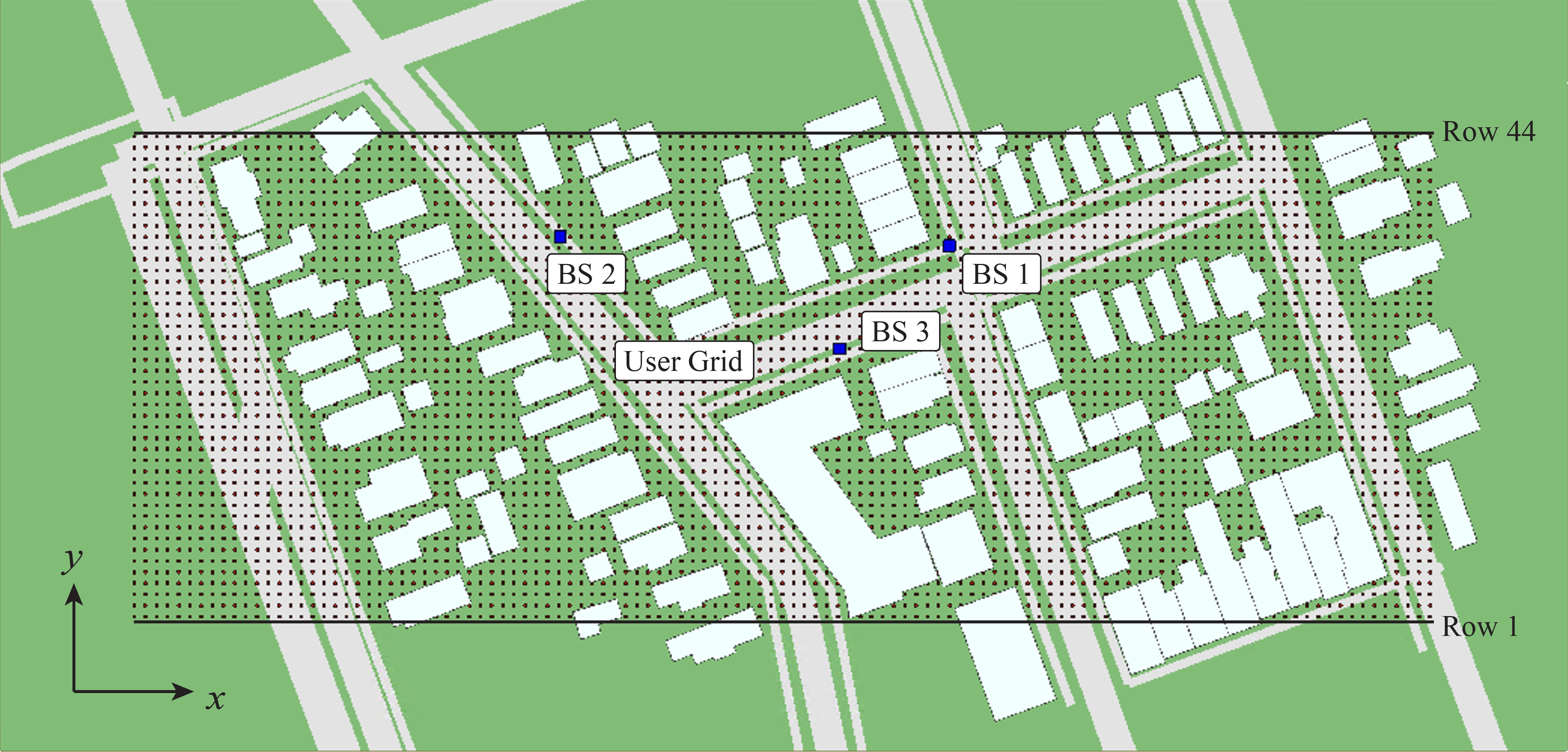
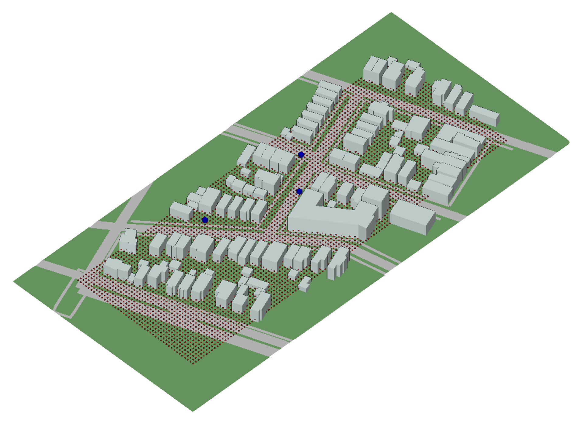
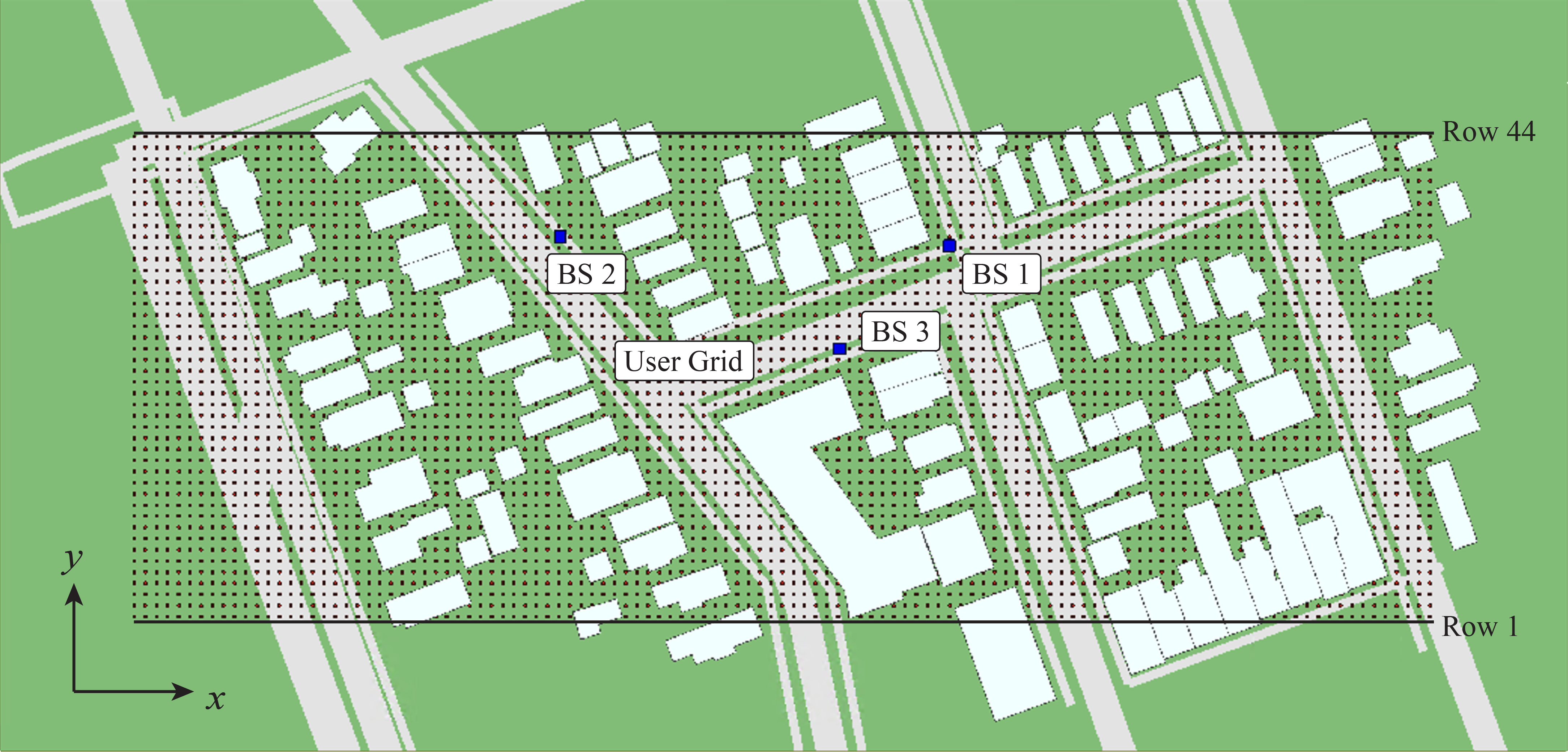
Figure 1. LoS status of users
Figure 2. Time of arrival
Figure 3. Path loss
Figure 4. Phase
Figure 5. Main path Direction of Arrival (azimuth)
Figure 6. Main path Direction of Arrival (elevation)
Figure 7. Main path Direction of Departure (azimuth)
Figure 8. Main path Direction of Departure (elevation)
Figure 9. Main path number of bounces
Figure 10. Main path first bounce type
Figure 11. Main path bounce profile
Download the ray-tracing data files of the ASU Campus 1 Scenario
- 3.5 GHz operating frequency: ‘ASU_Campus1_Scenario’ (zipped file) or ‘ASU_Campus1_Scenario’ (folder)
Applications of the Boston5G scenario
Previous slide
Next slide