
DeepMIMO v3 - Matlab and Octave
Table of Contents
DeepMIMO v3 Features
-
Includes all features of DeepMIMO v1 and v2
-
Optimized memory requirements and generation speed
-
Antenna panel orientation and field of view
- Dual polar antenna (when available in the scenario)
-
Doppler shift for the dynamic scenarios
-
Faster and more efficient data structure
-
Available in Matlab & Python
How Does it Work?
DeepMIMO v3 dataset generator processes the input ray-tracing file based on the parameters’ values specified in the DeepMIMO parameters file to generate the output dataset
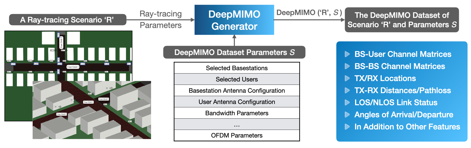
Check the detailed documentation below for more information about the DeepMIMO v3 parameters and outputs
Download and Installation
Step 1: (Generator scripts)
- Download DeepMIMO v3 MATLAB generator scripts.
- Extract the file DeepMIMOv3-matlab.zip
Step 2: (Scenario)
- Select and download a scenario from the scenarios page.
- Extract scenario folder into the path DeepMIMOv3/Raytracing_scenarios/
Step 3: (Parameter Configuration)
- Configure DeepMIMO parameters in parameters.m file.
Step 4: (Data Generation)
- Edit and run DeepMIMO_Dataset_Generator.m to configure and generate the dataset.
Input Parameters
scenario string
Name of the scenario to be loaded. To check and download available scenarios, please see the scenarios page.
scene_first, scene_last integers
[For dynamic scenarios] Determines the range of dynamic scenario scenes to be loaded [scene_first, scene_last]
active_BS integer array of active BSs
The ID of the basestations to be included in the dataset. The basestation IDs can be selected from the scenario description. In the final dataset, the activated basestations IDs are renumbered in the same order starting from 1 to the number of active basestations.
active_user_first, active_user_last integers
The range of rows are determined by these parameters.
Specifically, the row of users with the ID in the range [active_user_first, active_user_last] are selected.
row_subsampling float in the range (0, 1]
This parameter determines the ratio of the rows to be activated within the interval [active_user_first, active_user_last].
Speficially, it randomly samples round(row_subsampling*(active_user_last-active_user_first)) rows within the given interval.
The value 1 activates all the rows within the interval.
user_subsampling float in the range (0,1)
This parameter determines the ratio of the users to be activated within the active rows determined by the parameters user_subsampling, active_user_first and active_user_last. In each row, it allows random sampling of round(user_subsampling*number_of_users_in_row) users for activation.
The value 1 activates all the users within the active rows.
num_ant_BS integer array of 2 dimensions, ant_spacing_BS float
The basestation antenna parameters. num_ant represent the number of antenna elements in horizontal-vertical directions, e.g., [4, 2] for a UPA with 4 rows (horizontal) by 2 columns (vertical) antennas. The antenna spacing between array elements is determined as (ant_spacing x wavelength).
An antenna array (UPA) of (num_ant(1) x num_ant(2)) elements is adopted for each active basestation.
The axes of the antennas match the axes of the ray-tracing scenario.
If there are multiple active antennas, a matrix of 2 dimensional panel sizes can be given as input. For example, if basestations 3 and 4 are activated, the num_ant can be set as [[1, 1]; [4, 1]], equipping basestation 3 with a single antenna and basestation 4 with a ULA of 4 antenna elements.
num_ant_UE integer array of 2 dimensions, ant_spacing_UE float
The UE antenna parameters. num_ant_UE represent the number of antenna elements in horizontal-vertical directions, e.g., [4, 2] for a UPA with 4 rows (horizontal) by 2 columns (vertical) antennas.
The antenna spacing between array elements is determined as (ant_spacing_UE x wavelength).
An antenna array (UPA) of (num_ant_UE(1) x num_ant_UE(2)) elements is adopted for each active UE.
The axes of the antennas match the axes of the ray-tracing scenario.
array_rotation_BS float array of 3 dimensions
The BS antenna array rotation parameters, which consists of three rotation angles (in degrees). These angles rotate the BS antenna array in the given angles around the local x, y, z axes, respectively. To assign the same array rotation parameters to all active BSs, the following variable setting can be applied.
Note: By default, with the parameter being [0, 0, 0], the antenna is rotated towards the +x direction and placed along the y and z axes. [0, 0, -90] rotates the antenna towards -y direction.
params.array_rotation_BS = [x_rot, y_rot, z_rot]
Alternative setting (different parameters for multiple BSs)
To assign different array rotation parameters to each active BS, set an N x 3 matrix, with N being the number of active BSs. For instance, with two active BSs, the following variable setting can be applied.
					params.array_rotation_BS = [x_rot_1, y_rot_1, z_rot_1;
                            x_rot_2, y_rot_2, z_rot_2]
array_rotation_UE float array of 3 dimensions
The UE antenna array rotation parameters, which consists of three rotation angles (in degrees). These angles rotate the UE antenna array in the given angles around the local x, y, z axes, respectively. To assign the same array rotation parameters to all UEs, the following variable setting can be applied.
Note: By default, with the parameter being [0, 0, 0], the antenna is rotated towards the +x direction and placed along the y and z axes. [0, 0, -90] rotates the antenna towards -y direction.
params.array_rotation_UE = [x_rot, y_rot, z_rot]
Alternative setting (random parameters)
To assign uniformly random array rotations to each UE, set a 3 x 2 matrix, where the first column defines the lower limits of the uniform distribution, and the second column defines the upper limits. For instance, for each UE, uniformly random values between the minimum and the maximum limits can be assigned for the array rotation angles as follows.
					params.array_rotation_UE = [x_rot_min, x_rot_max;
                            y_rot_min, y_rot_max;
                            z_rot_min, z_rot_max]
FoV_ant_BS, FoV_ant_UE float array of 2 dimensions
The BS/UE antenna array field of view (FoV) parameters, which consists of two – horizontal and vertical – angles (in degrees). These angles limit the BS/UE antenna array FoV in the given angles around the antenna direction determined by the rotation. For instance, for a 360 degrees FoV, i.e., all the the paths are included in the channel computation, set this parameter to [360, 180]. If one prefers to have an antenna only receives the paths from the half space of the antenna, it should be set to [180, 180].
					params.FoV_ant_BS = [horizontal_FoV, vertical_FoV]
params.FoV_ant_UE = [horizontal_FoV, vertical_FoV]
radiation_pattern boolean
(0) activate isotropic radiation patterns for each BS and user antenna element
(1) activate half-wave dipole radiation patterns for each BS and user antenna element
bandwidth float
Total bandwidth of the channel in GHz.
activate_RX_filter boolean
Activate (1) receive LPF for OFDM channels.
generate_OFDM_channels boolean
(0) activate time domain (TD) channel impulse response generation.
(1) activate frequency domain (FD) channel generation for OFDM systems.
num_paths integer in [1, 25]
Maximum number of paths to be considered (a value between 1 and 25), e.g., choose 1 if you are only interested in the strongest path
num_OFDM integer
Number of OFDM subcarriers (e.g., 256, 512, 1024)
OFDM_sampling array of integers
The constructed channels will be calculated only at the given subcarriers to reduce the size of the dataset. For example, OFDM_sampling = [1] only generates the channels for the first OFDM subcarrier. Similarly, every 8th subcarrier can be generated with OFDM_sampling = [8:8:params.num_OFDM]. With this selection, the resulting subcarriers will be {8, 16, 24, 32, 40, …}.
enable_Doppler boolean
If activated, the Doppler shift will be reflected to the channels.
Note: This option only works with the scenarios with Doppler shift (new dynamic scenarios).
dual_polar boolean
The channels for the cross polar antennas (horizontal and vertical polarization) will be generated. The number of antennas provided in the parameters num_ant_BS and num_ant_UE will be doubled if this option is activated.
Note: This option only works with the scenarios with dual polar data.
Output Parameters
Output Variables of Basestation i – User j
Channel Matrix
DeepMIMO_dataset{i}.user{j}.channel
Type and Dimensions:
(a) Frequency-domain channel matrix (activate_FD_channels=1)
Float matrix of size (number of RX antennas) x (number of TX antennas) x (number of OFDM subcarriers)
(b) Time-domain channel matrix (activate_FD_channels=0)
Float matrix of size (number of RX antennas) x (number of TX antennas) x (number of channel paths)
Description: The channel matrix between basestation i and user j. Each of the first two dimensions follows a certain reshaping sequence that can be obtained using the following function:
antennamap = antenna_channel_map(params.num_ant_x, params.num_ant_y, params.num_ant_z, 1);
Returns a vector antennamap; each entry in the vector has 3 integers in the form of ‘x y z’ representing the antenna index of the channel element in the x, y, z directions
Note: The DeepMIMO generator does not apply an array based normalization for the power. The details on the channel generation can be found in the channel generation document at the bottom of this page.
Line-of-Sight Status
DeepMIMO_dataset{i}.user{j}.LoS_status
Type and Dimensions: Integer of values {-1, 0, 1}
Description: The variable that indicates the existence of the LOS path in the channel.
The values correspond to
(1): The LoS path exists.
(0): Only NLoS paths exist. The LoS path is blocked (LoS blockage).
(-1): No paths exist between the transmitter and the receiver (Full blockage).
TX-RX Distance
DeepMIMO_dataset{i}.user{j}.distance
Type and Dimensions: Float
Description: The Euclidian distance between the RX and TX locations in meters.
Path loss
DeepMIMO_dataset{i}.user{j}.pathloss
Type and Dimensions: Float
Description: The combined path-loss of the channel between the RX and TX in dB.
User Location
DeepMIMO_dataset{i}.user{j}.loc
Type and Dimensions: Float array of 3 dimensions
Description: The Euclidian location of the user in the form of [x, y, z].
Basestation Location
DeepMIMO_dataset{i}.loc
Type and Dimensions: Float array of 3 dimensions
Description: The Euclidian location of the user in the form of [x, y, z].
User Rotation
DeepMIMO_dataset{i}.user{j}.rotation
Type and Dimensions: Float array of 3 dimensions
Description: The rotation applied to the UE antenna array in the form of [x_rot, y_rot, z_rot], corresponding to the three rotation angles (in degrees) around the local x-y-z axes
Basestation Rotation
DeepMIMO_dataset{i}.rotation
Type and Dimensions: Float array of 3 dimensions
Description: The rotation applied to the BS antenna array in the form of [x_rot, y_rot, z_rot], corresponding to the three rotation angles (in degrees) around the local x-y-z axes
Ray-tracing Path Parameters
DeepMIMO_dataset{i}.user{j}.path_params
Type and Dimensions: Structure
Description: The parameters of the ray tracing is provided within the struct. Specifically, for each path
- Azimuth and zenith angle-of-arrival (DoA_phi, DoA_theta)
- Azimuth and zenith angle-of-departure (DoD_phi, DoD_theta)
- Time of arrival (ToA)
- Phase (phase)
- Power (power)
- Number of paths (num_paths)
are provided in this struct.
Azimuth Angles of Departure
Type and Dimensions: Float array of size (number of channel paths)
Description: The azimuth angles (directions) of departure from basestation i, for every channel path traveling from basestation i to user j
DeepMIMO_dataset{i}.user{j}.path_params.DoD_phi
Zenith Angles of Departure
DeepMIMO_dataset{i}.user{j}.path_params.DoD_theta
Type and Dimensions: Float array of size (number of channel paths)
Description: The zenith angles (directions) of departure from basestation i, for every channel path traveling from basestation i to user j
Azimuth Angles of Arrival
DeepMIMO_dataset{i}.user{j}.path_params.DoA_phi
Type and Dimensions: Float array of size (number of channel paths)
Description: The azimuth angles (directions) of arrival at user j, for each channel path traveling from basestation i to user j
Zenith Angles of Arrival
DeepMIMO_dataset{i}.user{j}.path_params.DoA_theta
Type and Dimensions: Float array of size (number of channel paths)
Description: The zenith angles (directions) of arrival at user j, for each channel path traveling from basestation i to user j
Channel Path Power
DeepMIMO_dataset{i}.user{j}.path_params.power
Type and Dimensions: Float array of size (number of channel paths)
Description: The channel path power of every channel path traveling from basestation i to user j in watts
Channel Path Phase
DeepMIMO_dataset{i}.user{j}.path_params.phase
Type and Dimensions: Float array of size (number of channel paths)
Description: The channel path phase of every channel path traveling from basestation i to user j
Note: These phase values are the channel phase shift values before accounting for the phase shifts due to the path propagation delays
Time of Arrival
DeepMIMO_dataset{i}.user{j}.path_params.ToA
Type and Dimensions: Float array of size (number of channel paths)
Description: The time delay of each channel path traveling from basestation i to user j. Each slice from the third dimension of the time domain channel matrix corresponds to a value in the ToA array.
Number of Paths
DeepMIMO_dataset{i}.user{j}.path_params.num_paths
Type and Dimensions: Float
Description: The number of paths accounted for when constructing the channel between basestation i and user j.
Time of Arrival*
DeepMIMO_dataset{i}.user{j}.ToA
*Note: This is the same array available in path_params.ToA. We copied it here to simplify accessing it when activate_FD_channels=0.
Type and Dimensions: Float array of size (number of channel paths)
Description: The time delay of each channel path traveling from basestation i to user j. Each slice from the third dimension of the time domain channel matrix corresponds to a value in the ToA array.
This information is available only if activate_FD_channels=0 (time-domain channel impulse response).
Otherwise, it can be found under the path_params structure as explained next.
Output Variables of Basestation i – User j at Scene s
Channel Matrix
DeepMIMO_dataset{s}{i}.user{j}.channel
Type and Dimensions:
(a) Frequency-domain channel matrix (activate_FD_channels=1)
Float matrix of size (number of RX antennas) x (number of TX antennas) x (number of OFDM subcarriers)
(b) Time-domain channel matrix (activate_FD_channels=0)
Float matrix of size (number of RX antennas) x (number of TX antennas) x (number of channel paths)
Description: The channel matrix between basestation i and user j. Each of the first two dimensions follows a certain reshaping sequence that can be obtained using the following function:
antennamap = antenna_channel_map(params.num_ant_x, params.num_ant_y, params.num_ant_z, 1);
Returns a vector antennamap; each entry in the vector has 3 integers in the form of ‘x y z’ representing the antenna index of the channel element in the x, y, z directions.
Note: The DeepMIMO generator does not apply an array based normalization for the power. The details on the channel generation can be found in the channel generation document at the bottom of this page.
Line-of-Sight Status
DeepMIMO_dataset{s}{i}.user{j}.LoS_status
Type and Dimensions: Integer of values {-1, 0, 1}
Description: The variable that indicates the existence of the LOS path in the channel.
The values correspond to
(1): The LoS path exists.
(0): Only NLoS paths exist. The LoS path is blocked (LoS blockage).
(-1): No paths exist between the transmitter and the receiver (Full blockage).
TX-RX Distance
DeepMIMO_dataset{s}{i}.user{j}.distance
Type and Dimensions: Float
Description: The Euclidian distance between the RX and TX locations in meters.
Path loss
DeepMIMO_dataset{s}{i}.user{j}.pathloss
Type and Dimensions: Float
Description: The combined path-loss of the channel between the RX and TX in dB.
User Location
DeepMIMO_dataset{s}{i}.user{j}.loc
Type and Dimensions: Float array of 3 dimensions
Description: The Euclidian location of the user in the form of [x, y, z].
Basestation Location
DeepMIMO_dataset{s}{i}.loc
Type and Dimensions: Float array of 3 dimensions
Description: The Euclidian location of the user in the form of [x, y, z].
User Rotation
DeepMIMO_dataset{s}{i}.user{j}.rotation
Type and Dimensions: Float array of 3 dimensions
Description: The rotation applied to the UE antenna array in the form of [x_rot, y_rot, z_rot], corresponding to the three rotation angles (in degrees) around the local x-y-z axes
Basestation Rotation
DeepMIMO_dataset{s}{i}.rotation
Type and Dimensions: Float array of 3 dimensions
Description: The rotation applied to the BS antenna array in the form of [x_rot, y_rot, z_rot], corresponding to the three rotation angles (in degrees) around the local x-y-z axes
Ray-tracing Path Parameters
DeepMIMO_dataset{s}{i}.user{j}.path_params
Type and Dimensions: Structure
Description: The parameters of the ray tracing is provided within the struct. Specifically, for each path
- Azimuth and zenith angle-of-arrival (DoA_phi, DoA_theta)
- Azimuth and zenith angle-of-departure (DoD_phi, DoD_theta)
- Time of arrival (ToA)
- Phase (phase)
- Power (power)
- Number of paths (num_paths)
are provided in this struct.
Azimuth Angles of Departure
DeepMIMO_dataset{s}{i}.user{j}.path_params.DoD_phi
Type and Dimensions: Float array of size (number of channel paths)
Description: The azimuth angles (directions) of departure from basestation i, for every channel path traveling from basestation i to user j
Zenith Angles of Departure
DeepMIMO_dataset{s}{i}.user{j}.path_params.DoD_theta
Type and Dimensions: Float array of size (number of channel paths)
Description: The zenith angles (directions) of departure from basestation i, for every channel path traveling from basestation i to user j
Azimuth Angles of Arrival
DeepMIMO_dataset{s}{i}.user{j}.path_params.DoA_phi
Type and Dimensions: Float array of size (number of channel paths)
Description: The azimuth angles (directions) of arrival at user j, for each channel path traveling from basestation i to user j
Zenith Angles of Arrival
DeepMIMO_dataset{s}{i}.user{j}.path_params.DoA_theta
Type and Dimensions: Float array of size (number of channel paths)
Description: The zenith angles (directions) of arrival at user j, for each channel path traveling from basestation i to user j
Channel Path Power
DeepMIMO_dataset{s}{i}.user{j}.path_params.power
Type and Dimensions: Float array of size (number of channel paths)
Description: The channel path power of every channel path traveling from basestation i to user j in watts
Channel Path Phase
DeepMIMO_dataset{s}{i}.user{j}.path_params.phase
Type and Dimensions: Float array of size (number of channel paths)
Description: The channel path phase of every channel path traveling from basestation i to user j
Note: These phase values are the channel phase shift values before accounting for the phase shifts due to the path propagation delays
Time of Arrival
DeepMIMO_dataset{s}{i}.user{j}.path_params.ToA
Type and Dimensions: Float array of size (number of channel paths)
Description: The time delay of each channel path traveling from basestation i to user j. Each slice from the third dimension of the time domain channel matrix corresponds to a value in the ToA array.
Number of Paths
DeepMIMO_dataset{s}{i}.user{j}.path_params.num_paths
Type and Dimensions: Float
Description: The number of paths accounted for when constructing the channel between basestation i and user j.
Time of Arrival*
DeepMIMO_dataset{s}{i}.user{j}.ToA
* Note: This is the same array available in path_params.ToA. We copied it here to simplify accessing it when activate_FD_channels=0.
Type and Dimensions: Float array of size (number of channel paths)
Description: The time delay of each channel path between basestation i and user j. Each slice from the third dimension of the time domain channel matrix corresponds to a value in the ToA array.
This information is available only if activate_FD_channels=0 (time-domain channel impulse response).
Otherwise, it can be found under the path_params structure as explained next.
Output Variables of Basestation i – Basestation j
Channel Matrix
DeepMIMO_dataset{i}.basestation{j}.channel
Type and Dimensions:
(a) Frequency-domain channel matrix (activate_FD_channels=1)
Float matrix of size (number of RX antennas) x (number of TX antennas) x (number of OFDM subcarriers)
(b) Time-domain channel matrix (activate_FD_channels=0)
Float matrix of size (number of RX antennas) x (number of TX antennas) x (number of channel paths)
Description: The channel matrix between basestation i and basestation j. Each of the first two dimensions follows a certain reshaping sequence that can be obtained using the following function:
antennamap = antenna_channel_map(params.num_ant_x, params.num_ant_y, params.num_ant_z, 1);
Returns a vector antennamap; each entry in the vector has 3 integers in the form of ‘x y z’ representing the antenna index of the channel element in the x, y, z directions
Note: The DeepMIMO generator does not apply an array based normalization for the power. The details on the channel generation can be found in the channel generation document at the bottom of this page.
Line-of-Sight Status
DeepMIMO_dataset{i}.basestation{j}.LoS_status
Type and Dimensions: Integer of values {-1, 0, 1}
Description: The variable that indicates the existence of the LOS path in the channel.
The values correspond to
(1): The LoS path exists.
(0): Only NLoS paths exist. The LoS path is blocked (LoS blockage).
(-1): No paths exist between the transmitter and the receiver (Full blockage).
TX-RX Distance
DeepMIMO_dataset{i}.basestation{j}.distance
Type and Dimensions: Float
Description: The Euclidian distance between the RX and TX locations in meters.
Path loss
DeepMIMO_dataset{i}.basestation{j}.pathloss
Type and Dimensions: Float
Description: The combined path-loss of the channel between the RX and TX in dBm.
RX Basestation Location
DeepMIMO_dataset{i}.basestation{j}.loc
Type and Dimensions: Float array of 3 dimensions
Description: The Euclidian location of the user in the form of [x, y, z].
TX Basestation Location
DeepMIMO_dataset{i}.loc
Type and Dimensions: Float array of 3 dimensions
Description: The Euclidian location of the user in the form of [x, y, z].
RX Basestation Rotation
DeepMIMO_dataset{i}.basestation{j}.rotation
Type and Dimensions: Float array of 3 dimensions
Description: The rotation applied to the RX BS antenna array in the form of [x_rot, y_rot, z_rot], corresponding to the three rotation angles (in degrees) around the local x-y-z axes
TX Basestation Rotation
DeepMIMO_dataset{i}.rotation
Type and Dimensions: Float array of 3 dimensions
Description: The rotation applied to the TX BS antenna array in the form of [x_rot, y_rot, z_rot], corresponding to the three rotation angles (in degrees) around the local x-y-z axes
Ray-tracing Path Parameters
DeepMIMO_dataset{i}.basestation{j}.path_params
Type and Dimensions: Structure
Description: The parameters of the ray tracing is provided within the struct. Specifically, for each path
- Azimuth and zenith angle-of-arrival (DoA_phi, DoA_theta)
- Azimuth and zenith angle-of-departure (DoD_phi, DoD_theta)
- Time of arrival (ToA)
- Phase (phase)
- Power (power)
- Number of paths (num_paths)
are provided in this struct.
Azimuth Angles of Departure
DeepMIMO_dataset{i}.basestation{j}.path_params.DoD_phi
Type and Dimensions: Float array of size (number of channel paths)
Description: The azimuth angles (directions) of departure from basestation i, for every channel path traveling from basestation i to basestation j
Zenith Angles of Departure
DeepMIMO_dataset{i}.basestation{j}.path_params.DoD_theta
Type and Dimensions: Float array of size (number of channel paths)
Description: The zenith angles (directions) of departure from basestation i, for every channel path traveling from basestation i to basestation j
Azimuth Angles of Arrival
DeepMIMO_dataset{i}.basestation{j}.path_params.DoA_phi
Type and Dimensions: Float array of size (number of channel paths)
Description: The azimuth angles (directions) of arrival at basestation j, for each channel path traveling from basestation i to basestation j
Zenith Angles of Arrival
DeepMIMO_dataset{i}.basestation{j}.path_params.DoA_theta
Type and Dimensions: Float array of size (number of channel paths)
Description: The zenith angles (directions) of arrival at basestation j, for each channel path traveling from basestation i to basestation j
Channel Path Power
DeepMIMO_dataset{i}.basestation{j}.path_params.power
Type and Dimensions: Float array of size (number of channel paths)
Description: The channel path power of every channel path traveling from basestation i to basestation j in watts
Channel Path Phase
DeepMIMO_dataset{i}.basestation{j}.path_params.phase
Type and Dimensions: Float array of size (number of channel paths)
Description: The channel path phase of every channel path traveling from basestation i to basestation j
Note: These phase values are the channel phase shift values before accounting for the phase shifts due to the path propagation delays
Time of Arrival
DeepMIMO_dataset{i}.basestation{j}.path_params.ToA
Type and Dimensions: Float array of size (number of channel paths)
Description: The time delay of each channel path traveling from basestation i to basestation j. Each slice from the third dimension of the time domain channel matrix corresponds to a value in the ToA array.
Number of Paths
DeepMIMO_dataset{i}.basestation{j}.path_params.num_paths
Type and Dimensions: Float
Description: The number of paths accounted for when constructing the channel between basestation i and basestation j.
Time of Arrival*
DeepMIMO_dataset{i}.basestation{j}.ToA
* Note: This is the same array available in path_params.ToA. We copied it here to simplify accessing it when activate_FD_channels=0.
Type and Dimensions: Float array of size (number of channel paths)
Description: The time delay of each channel path between basestation i and basestation j. Each slice from the third dimension of the time domain channel matrix corresponds to a value in the ToA array.
This information is available only if activate_FD_channels=0 (time-domain channel impulse response).
Otherwise, it can be found under the path_params structure as explained next.
Output Variables of Basestation i – Basestation j at Scene s
Channel Matrix
DeepMIMO_dataset{s}{i}.basestation{j}.channel
Type and Dimensions:
(a) Frequency-domain channel matrix (activate_FD_channels=1)
Float matrix of size (number of RX antennas) x (number of TX antennas) x (number of OFDM subcarriers)
(b) Time-domain channel matrix (activate_FD_channels=0)
Float matrix of size (number of RX antennas) x (number of TX antennas) x (number of channel paths)
Description: The channel matrix between basestation i and basestation j. Each of the first two dimensions follows a certain reshaping sequence that can be obtained using the following function:
antennamap = antenna_channel_map(params.num_ant_x, params.num_ant_y, params.num_ant_z, 1);
Returns a vector antennamap; each entry in the vector has 3 integers in the form of ‘x y z’ representing the antenna index of the channel element in the x, y, z directions
Note: The DeepMIMO generator does not apply an array based normalization for the power. The details on the channel generation can be found in the channel generation document at the bottom of this page.
Line-of-Sight Status
DeepMIMO_dataset{s}{i}.basestation{j}.LoS_status
Type and Dimensions: Integer of values {-1, 0, 1}
Description: The variable that indicates the existence of the LOS path in the channel.
The values correspond to
(1): The LoS path exists.
(0): Only NLoS paths exist. The LoS path is blocked (LoS blockage).
(-1): No paths exist between the transmitter and the receiver (Full blockage).
TX-RX Distance
DeepMIMO_dataset{s}{i}.basestation{j}.distance
Type and Dimensions: Float
Description: The Euclidian distance between the RX and TX locations in meters.
Path loss
DeepMIMO_dataset{s}{i}.basestation{j}.pathloss
Type and Dimensions: Float
Description: The combined path-loss of the channel between the RX and TX in dB.
RX Basestation Location
DeepMIMO_dataset{s}{i}.basestation{j}.loc
Type and Dimensions: Float array of 3 dimensions
Description: The Euclidian location of the user in the form of [x, y, z].
TX Basestation Location
DeepMIMO_dataset{s}{i}.loc
Type and Dimensions: Float array of 3 dimensions
Description: The Euclidian location of the user in the form of [x, y, z].
RX Basestation Rotation
DeepMIMO_dataset{s}{i}.basestation{j}.rotation
Type and Dimensions: Float array of 3 dimensions
Description: The rotation applied to the RX BS antenna array in the form of [x_rot, y_rot, z_rot], corresponding to the three rotation angles (in degrees) around the local x-y-z axes
TX Basestation Rotation
DeepMIMO_dataset{s}{i}.rotation
Type and Dimensions: Float array of 3 dimensions
Description: The rotation applied to the TX BS antenna array in the form of [x_rot, y_rot, z_rot], corresponding to the three rotation angles (in degrees) around the local x-y-z axes
Ray-tracing Path Parameters
DeepMIMO_dataset{s}{i}.basestation{j}.path_params
Type and Dimensions: Structure
Description: The parameters of the ray tracing is provided within the struct. Specifically, for each path
- Azimuth and zenith angle-of-arrival (DoA_phi, DoA_theta)
- Azimuth and zenith angle-of-departure (DoD_phi, DoD_theta)
- Time of arrival (ToA)
- Phase (phase)
- Power (power)
- Number of paths (num_paths)
are provided in this struct.
Azimuth Angles of Departure
DeepMIMO_dataset{s}{i}.basestation{j}.path_params.DoD_phi
Type and Dimensions: Float array of size (number of channel paths)
Description: The azimuth angles (directions) of departure from basestation i, for every channel path traveling from basestation i to basestation j
Zenith Angles of Departure
DeepMIMO_dataset{s}{i}.basestation{j}.path_params.DoD_theta
Type and Dimensions: Float array of size (number of channel paths)
Description: The zenith angles (directions) of departure from basestation i, for every channel path traveling from basestation i to basestation j
Azimuth Angles of Arrival
DeepMIMO_dataset{s}{i}.basestation{j}.path_params.DoA_phi
Type and Dimensions: Float array of size (number of channel paths)
Description: The azimuth angles (directions) of arrival at basestation j, for each channel path traveling from basestation i to basestation j
Zenith Angles of Arrival
DeepMIMO_dataset{s}{i}.basestation{j}.path_params.DoA_theta
Type and Dimensions: Float array of size (number of channel paths)
Description: The zenith angles (directions) of arrival at basestation j, for each channel path traveling from basestation i to basestation j
Channel Path Power
DeepMIMO_dataset{s}{i}.basestation{j}.path_params.power
Type and Dimensions: Float array of size (number of channel paths)
Description: The channel path power of every channel path traveling from basestation i to basestation j in watts
Channel Path Phase
DeepMIMO_dataset{s}{i}.basestation{j}.path_params.phase
Type and Dimensions: Float array of size (number of channel paths)
Description: The channel path phase of every channel path traveling from basestation i to basestation j
Note: These phase values are the channel phase shift values before accounting for the phase shifts due to the path propagation delays
Time of Arrival
DeepMIMO_dataset{s}{i}.basestation{j}.path_params.ToA
Type and Dimensions: Float array of size (number of channel paths)
Description: The time delay of each channel path traveling from basestation i to basestation j. Each slice from the third dimension of the time domain channel matrix corresponds to a value in the ToA array.
Number of Paths
DeepMIMO_dataset{s}{i}.basestation{j}.path_params.num_paths
Type and Dimensions: Float
Description: The number of paths accounted for when constructing the channel between basestation i and basestation j.
Time of Arrival*
DeepMIMO_dataset{s}{i}.basestation{j}.ToA
* Note: This is the same array available in path_params.ToA. We copied it here to simplify accessing it when activate_FD_channels=0.
Type and Dimensions: Float array of size (number of channel paths)
Description: The time delay of each channel path between basestation i and basestation j. Each slice from the third dimension of the time domain channel matrix corresponds to a value in the ToA array.
This information is available only if activate_FD_channels=0 (time-domain channel impulse response).
Otherwise, it can be found under the path_params structure as explained next.
Examples
Example 1: Introduction to the DeepMIMOv3 Generator
The functions used in this example
The main script used to illustrate 'Example 1'
The 'parameters' file used in generating 'Example 1' outputs
